That right there is an implementation of BitClock. Back in January I wrote a blog post titled Refactoring BitClock about how I was reviving and expanding the project, and how I'd love to build a hardware implementation some day. Well, today is that day!
LED Matrix
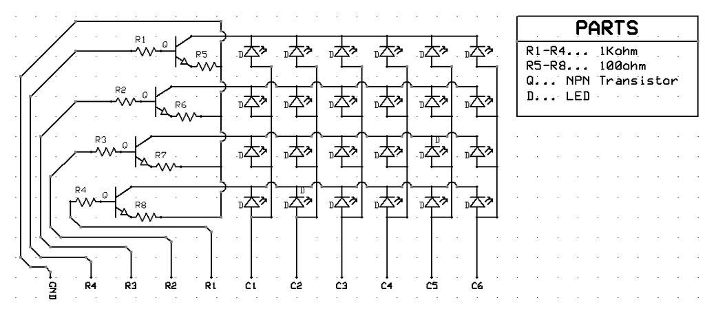
The core of the design is a 6x4 matrix of Light Emitting Diodes (LEDs). The LED board will be controlled by some microcontroller and a Real-Time Clock (RTC) module. I'm still quite inexperienced when it comes to electronics design, so I'm basically building the LED board as per Easy 4×6 LED Matrix, Arduino!, a tutorial on building and programming such a matrix.

Each of the columns labelled C1 - C6 represents a column in the matrix. When the Arduino outputs electricity on one of these lines it might flow through any of the LEDs in that column. To the left of the LED matrix are 4 NPN transistors which we will use to switch a row "on" or "off".
Each transistor has three lines: a Collector, which takes some input signal; a Base, which controls the state of the transistor; and an Emitter, which outputs some voltage determined by the Collector and Base inputs. The outputs of each row become the inputs to that row's transistor's Collector. If the Arduino applies power to that transistor's Base then the transistor will be in the "on" state and electricity will flow from the Collector to the Emitter out to ground. If the Arduino is not applying any power to that transistor's Base then the transistor will be in the "off" state and electricity will not be able to flow through the transistor - or any LEDs in that row! For more information on how a transistor can be practically applied check out How Transistors Work - The Learning Circuit by element14. For more information on how a transistor physically works watch How Does a Transistor Work? by Veritasium.
Translated to a 24x18 hole bread board the components are laid out like this.
| GND | o | o | o | o | tCollect | o | Led - | o | o | Led - | o | o | Led - | o | o | Led - | o | o | Led - | o | o | Led - | o |
| GND | ROW1 | R1k+ | o | R1k- | tBase | o | o | Led + | o | o | Led + | o | o | Led + | o | o | Led + | o | o | Led + | o | o | Led + |
| GND | o | R100- | o | R100+ | tEmit | o | o | o | o | o | o | o | o | o | o | o | o | o | o | o | o | o | o |
| GND | o | o | o | o | tCollect | o | Led - | o | o | Led - | o | o | Led - | o | o | Led - | o | o | Led - | o | o | Led - | o |
| GND | ROW2 | R1k+ | o | R1k- | tBase | o | o | Led + | o | o | Led + | o | o | Led + | o | o | Led + | o | o | Led + | o | o | Led + |
| GND | o | R100- | o | R100+ | tEmit | o | o | o | o | o | o | o | o | o | o | o | o | o | o | o | o | o | o |
| GND | o | o | o | o | tCollect | o | Led - | o | o | Led - | o | o | Led - | o | o | Led - | o | o | Led - | o | o | Led - | o |
| GND | ROW3 | R1k+ | o | R1k- | tBase | o | o | Led + | o | o | Led + | o | o | Led + | o | o | Led + | o | o | Led + | o | o | Led + |
| GND | o | R100- | o | R100+ | tEmit | o | o | o | o | o | o | o | o | o | o | o | o | o | o | o | o | o | o |
| GND | o | o | o | o | tCollect | o | Led - | o | o | Led - | o | o | Led - | o | o | Led - | o | o | Led - | o | o | Led - | o |
| GND | ROW4 | R1k+ | o | R1k- | tBase | o | o | Led + | o | o | Led + | o | o | Led + | o | o | Led + | o | o | Led + | o | o | Led + |
| GND | o | R100- | o | R100+ | tEmit | o | o | o | o | o | o | o | o | o | o | o | o | o | o | o | o | o | o |
| GND | o | o | o | o | o | o | o | o | o | o | o | o | o | o | o | o | o | o | o | o | o | o | o |
| GND | o | o | o | o | o | o | o | COL1 | o | o | COL2 | o | o | COL3 | o | o | COL4 | o | o | COL5 | o | o | COL6 |
| GND | o | o | o | o | o | o | o | o | o | o | o | o | o | o | o | o | o | o | o | o | o | o | o |
| GND | o | o | o | o | o | o | o | o | o | o | o | o | o | o | o | o | o | o | o | o | o | o | o |
| GND | o | o | o | o | o | o | o | o | o | o | o | o | o | o | o | o | o | o | o | o | o | o | o |
| GND | o | o | o | o | o | o | o | o | o | o | o | o | o | o | o | o | o | o | o | o | o | o | o |
All together we can turn on a specific LED by applying voltage to both its column and row lines at the same time. To light up the upper-right LED you apply 5v to C6 and R4 simultaneously. Current will flow from the Arduino to C6 to your target LED to the R4 transistor to ground.
Matrix Multiplexing and Persistence of Vision
The trouble with such a matrix is that you can only turn on LEDs in contiguous rectangles. For example, you can't light only LEDs C6R4 and C5R3 at the same time. You'd need to apply voltage to lines C5, C6, R3, and R4. But doing so would turn on the LEDs C5R3, C5R4, C6R3, and C6R4. That's twice as many LEDs as we wanted!
To get around this limitation we'll need to rotate through each row, turn that row's transistor "on", and then activate each column in that row which should have an illuminated LED. This technique is called matrix multiplexing. If we rotate through the rows fast enough the brain can't perceive individual rows as on or off, but instead perceives them all on at once! This effect is called persistence of vision.
Progress
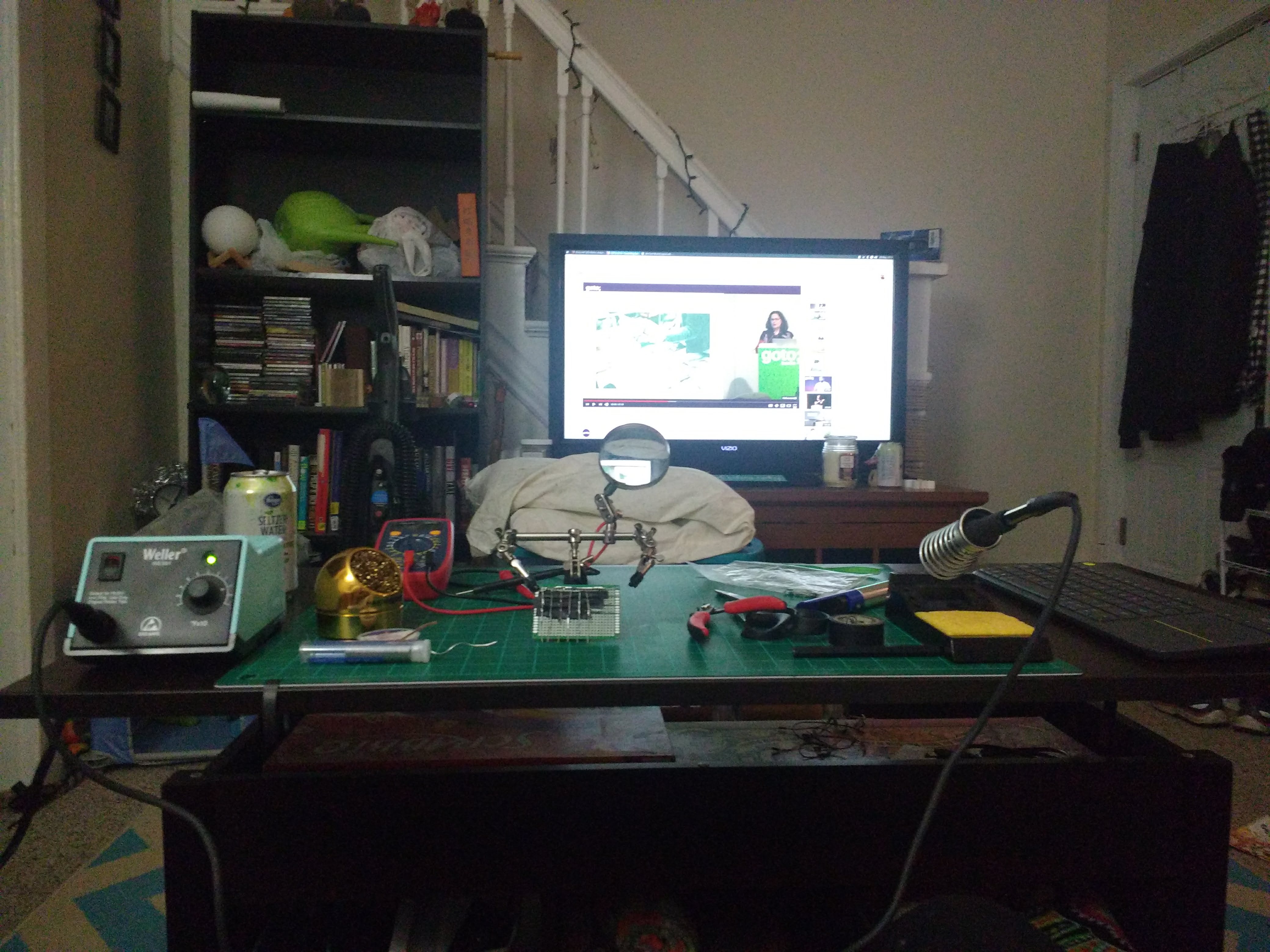
Thus far I've set up a workbench...

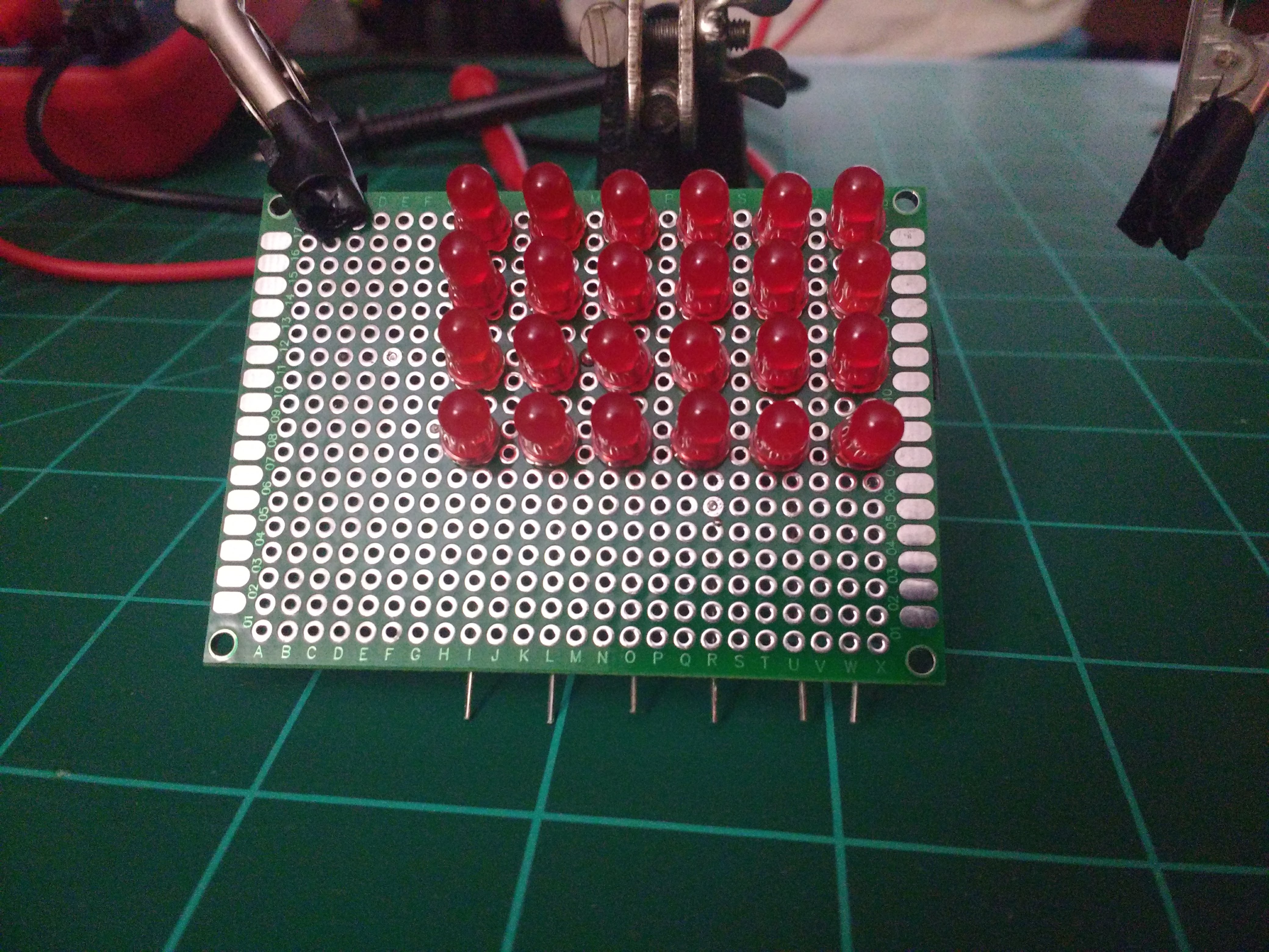
And soldered the LEDs on to the breadboard.

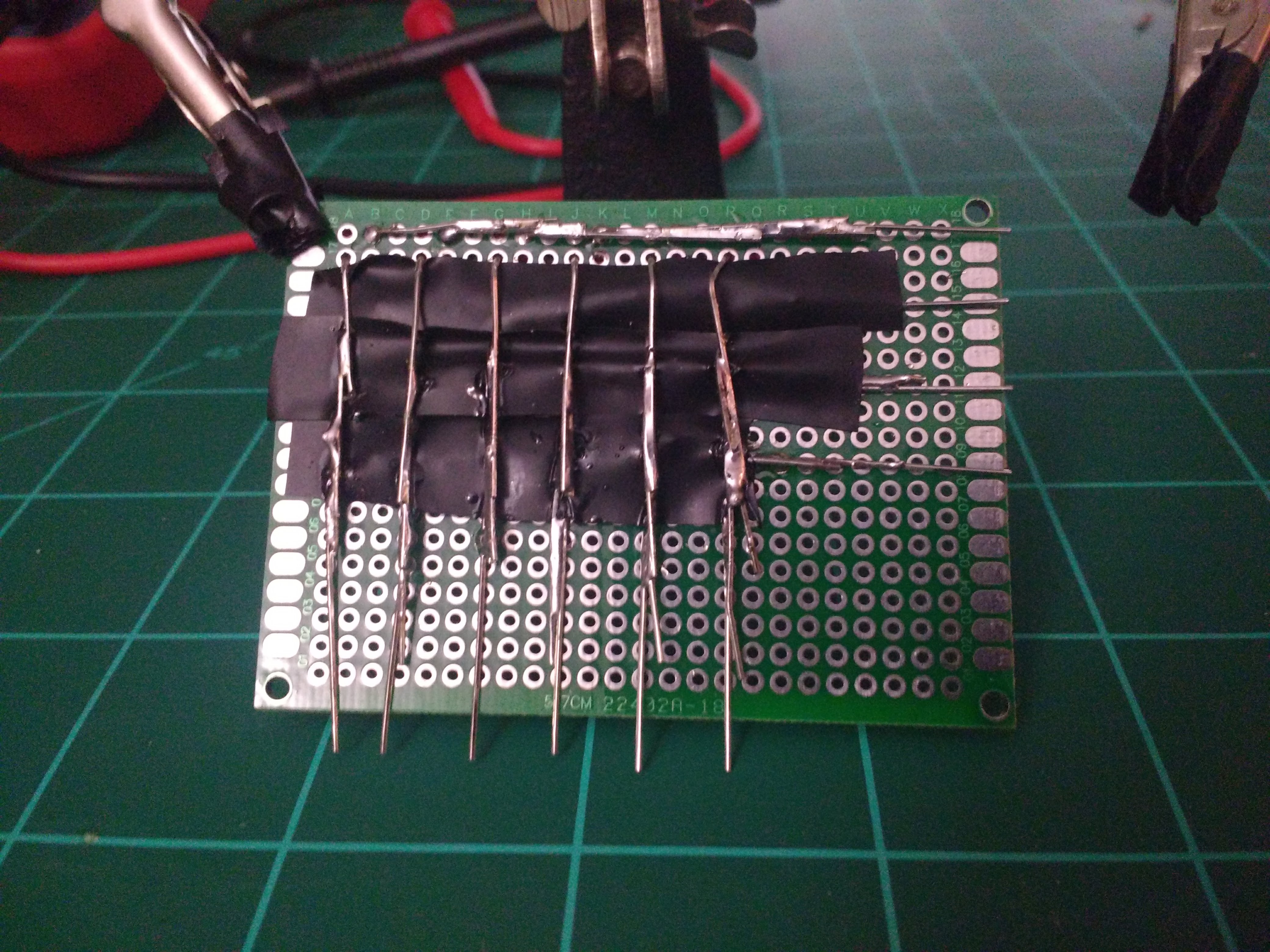
In the back you can see that I soldered the rows together into rails, separated rows and column rails with a layer of electrical tape, and soldered the columns into rails.

DONE.